Mini-Mapper 13: Starting software setup
Once we get the motor prototype boards built, we’re going to need some software to drive the thing. I’m going to be using an ST Micro Nucleo board with an STM32F767ZI microcontroller on it for experiments and initial software development. I’ve started doing some setup work and a couple of little demos with the Nucleo board to help me figure out how to work this.
Requirements
I have a few slightly unusual requirements for this (what a surprise, eh?). Here they are (justifications and explanations follow):
Language: not C! C++, maybe some Rust later
IDE: Emacs
Build system: Makefiles to start with, maybe Meson + Ninja later
Principle: No external abstractions; maximum internal abstractions
Languages
First, languages. Most hardware people go straight for C, but as someone with a programming background using very high level languages (mostly Haskell), I like to get the compiler to do as much for me as I can, and that means moving beyond C. However, I also want something where I can twiddle bits in registers directly (see “Principle” below…). That means that using Haskell or Scheme or something is not practicable. There has been a little bit of work on using Haskell in embedded systems, but it’s not really something I want to get into on this project.
The two best options then seem to be C++ or Rust. Rust is, I think, a nicer language, but it’s not one that I know too well yet, and I’m going to have enough things to learn without adding that to the list. I have written a fair bit of C++ code in the past, so even though I’m not familiar with more recent iterations of the C++ standard, it seems like a good choice. There’s also a reasonably sized community of people using C++ for embedded systems. For example, I just watched a great talk by Michael Caisse from a couple of years ago, all about modern C++ techniques for embedded development.
So, C++ it is.
IDEs
Then, IDEs… I’ve been doing some investigations with various IDEs for another project recently, and I just don’t enjoy them a whole lot. I don’t like the “closed garden” model they lead to. Also, I’ve been using Emacs for 25 years, and over all that time, I think it’s about the only piece of software I’ve never been tempted to abandon to find an alternative. Editor support for C and C++ in Emacs is a bit weird though. More “modern” languages (Python, Rust, Haskell, etc.) have good Emacs support, mostly because they have build systems that are mandated by the language. C and C++ are funny because the build system has traditionally been considered something separate from the language, so tooling is a bit scattered.
However, eglot +
clangd is just about
perfect. The only extra you need if you’re just using Makefiles (as
opposed to CMake or Meson or something) is some way to create a
compilation database (a compile_commands.json file), which you
can do using bear,
which I just run from an extra cdb make target.
Build systems
Which brings me on to build systems. Every build system is terrible, and life seems to be a continual quest to find the least terrible one. I’ve done stuff with Autotools, I’ve done stuff with CMake, I’ve done stuff with SCons. They’re all terrible in their own unique and terrible ways. For this project, I did start fooling around with CMake since it’s used by a lot of IDEs for embedded development. Hope versus experience. It gets me every time. I really don’t enjoy CMake at all. The language is terrible, the documentation is terrible, debugging is next to impossible.
So I ended up dropping that and just writing some Makefiles. Make is sort of terrible in its own way, but most of the terribleness of Make is something you inflict on yourself. (Variables defining variables that define variables? Check! Code generation macros? Check! Name generation macros? Check! State-dependent slurping of information from the filesystem in the middle of a build? Check!) I’ve seen other people comment on the effect where every Makefile you write quickly turns into the kind of Makefile that makes everyone hate Make. I’ll try to avoid that. The needs of this project should be simple enough to do that. And I might give Meson + Ninja a try, since a lot of people say that Meson is a less-than-terrible build system, which would be a miracle.
Principles
And finally, principles. What do I mean by “No external abstractions; maximum internal abstractions”? That sounds weird, right?
Most of the time when you’re doing embedded development, you use something like a HAL (Hardware Abstraction Layer), which is a library that removes you a step or two from some of the details of setting all the registers and things in your microcontroller to configure peripherals. It also usually makes it easier to switch between different processors (different parts from the same manufacturer anyway). For this project though, I don’t want to abstract the hardware, because I want to do all the setting of registers and get the deepest understanding of what’s going on in the microcontroller that’s possible. So I don’t really want a HAL. I just want a header file that gives me names for all the registers in the STM32F767ZI, so I can set things up myself following the documentation. (“The documentation” is 255 pages of datasheet, plus 1954 pages of reference manual for the chip, plus 315 pages of the ARM Cortex-M7 user guide, plus 858 pages for the ARMv7-M architecture manual. As far as I can tell, that’s quite a modest amount of documentation by industry standards!)
The ST Micro CMSIS libraries come with header files like this for each
of the STM32 chips. So all I need to do is include
stm32f767xx.h (and maybe stm32f7xx.h too), and I’ll be
off!
That’s the “no external abstractions” part dealt with: it’s all about
getting as close to the hardware as possible to understand what’s
going on, what the options are, why things need to be set up the way
they are, and so on. The other part, “maximum internal abstractions”,
is more about how I’m going to write my own code. I’m essentially
going to write a sort of application-specific HAL, but at a much
higher level than is normal in a typical vendor-supplied HAL. For
example, I might have a C++ class called MotorEncoder that
encapsulates all the details of detecting pulses from a motor encoder
and turning them into a measure of the speed of rotation of a wheel,
ranging from setting up the GPIO pin for input of the encoder pulses,
handling of interrupts on the pin, setting up the timer used to
measure the time between pulses, all the way to providing an
application-relevant API for motor control algorithms to use.
I’m very interested in the idea of “zero-cost abstractions” that has been pushed a lot by the Rust community, and is also reasonably well-known in the C++ community. This is the idea that you should be able to write code in a way that makes sense from an application or domain perspective and have the compiler do the work of turning it into an efficient representation for execution. For example, if you’re writing a state machine in C++, you can do it by hand, defining some constants to represent states, events, and so on, and having a big old switch statement to implement the state transitions. Or, you can use [Boost::ext].SML state machine language library, which gives you a clear domain-specific language for writing state machine descriptions, embedded in C++, that compiles to code that’s as efficient as a hand-written state machine, but using advanced type system methods, can give you much greater confidence in the correctness of your state machine implementation.
This stuff is not popular with most embedded developers, since it looks like magic, and it’s harder to map from the code you write to the assembler that the compiler produces. But it helps to produce code with less faults!
So that’s the theory. Let’s look at a couple of concrete things I did to get started. The code described here is all at the episode-013 tag of the project repository.
Minimal blinky
First thing, as a very basic demonstration, and to help with settingn up makefiles, a minimal blinky with no clock setup, no C++, blinking a single LED on the Nucleo board based on a SysTick timer.
I’m going to be making lots of little experimental programs and
libraries here, so I’ve started right from the beginning putting Make
definitions into a shared Makefile.common in the
bsp.
This directory also contains all the CMSIS header files I’m using, as
well as link scripts and startup files. These are taken from an
example generated using the
STM32CubeMX
configuration tool. Using that to get going quickly seemed like a
better idea than trying to write my own startup code from scratch.
Most of the configuration in the makefile comes direct from the
STM32CubeMX example, and I’ll probably be revisiting this stuff at
some point to understand it all properly. For the moment, we’ll just
accept that it does more or less the right thing.
The bsp/include directory will eventually contain board support
headers for various different boards (in particular, the final main
Mini-Mapper baord). For the moment, there’s just a bsp-nucleo.h
containing basic definitions for the Nucleo board I’m using, which are
basically just the pins with LEDs or buttons on, and the pins used for
the UART port connected to the ST-Link debugger on the board. The
other headers in the bsp directory are just the “core” CMSIS
headers, which for our puposes really just means the
stm32f767xx.h and stm32f7xx.h headers, plus the
core_cm7.h header that contains definitions that are common to
all Cortex-M7 devices. I might reorganise this stuff at some point to
remove all the other files that aren’t relevant to us here.
The
minimal-blink/main.cpp
file just does basic GPIO setup for one of the LED pins on the Nucleo
board, initialises the SysTick (using the SysTick_Config
function from the CMSIS Cortex-M7 support files), then toggles the LED
on and off, waiting in between using a delay function based on
counting SysTick events. I’m not sure what the initial clock setup is
if you don’t do anything explicit yourself, so the timing here is a
bit hit and miss. It was intended just as a test to get off the ground
and to get the Makefiles and CMSIS headers working.
Better blinky
The better-blink example adds a couple of things to the first minimal blinky.
First, there’s proper clock setup code. Slightly unfortunately, this is something you need to do more or less right at the start, before you can do anything else. I say “unfortunately”, because getting this right involves understanding at least part of this clock tree diagram, which is pretty intimidating the first time you see it:
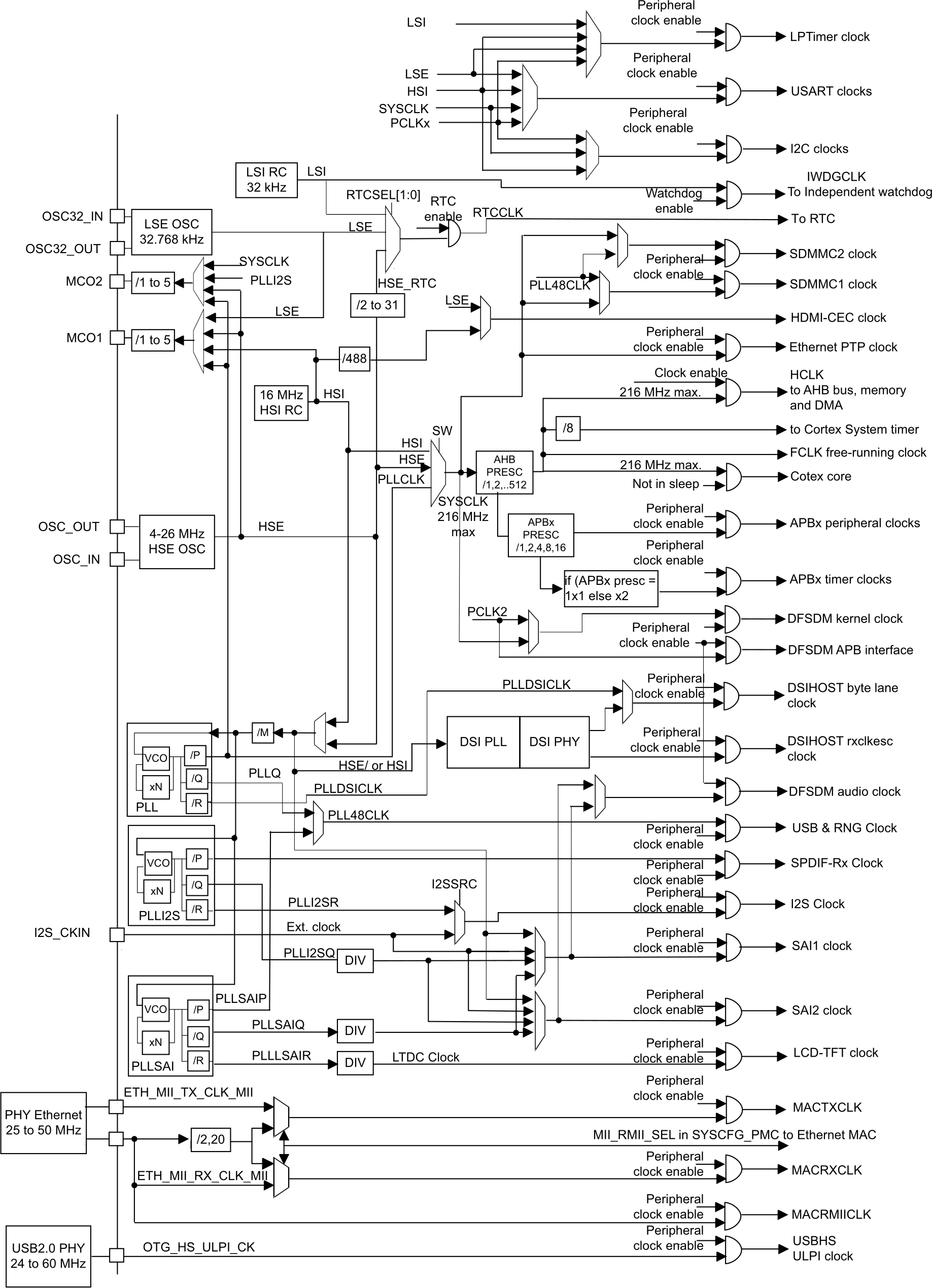
To start with, a lot of this can be ignored, since much of it is concerned with particular peripherals that we don’t need to begin with. The important thing is getting the system core clock going as we want it to, and getting the main bus clocks (AHB and APB) set up. For our purposes, we can focus on a small part of the clock tree, highlighted here in red:
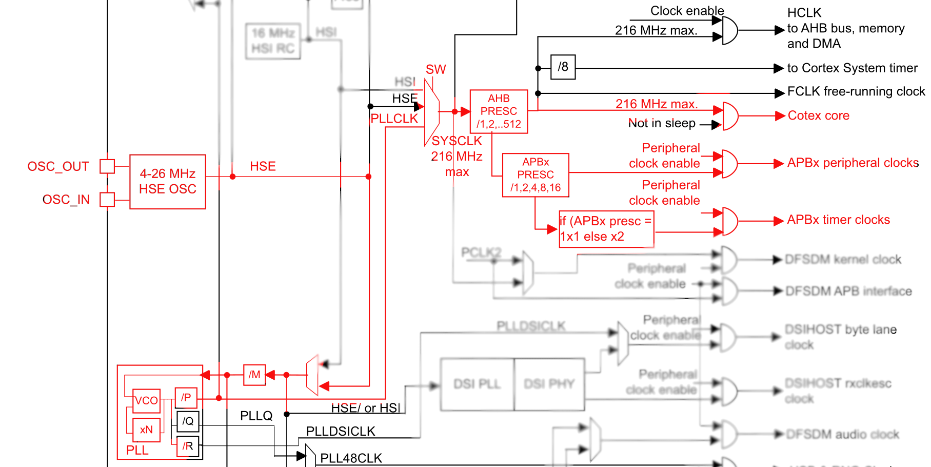
We want to get the system clock going as fast as we can. The maximum permitted clock frequency is 216 MHz, and the Nucleo board provides an 8 MHz input clock for us to work with. That means we can use the HSE (High Speed External) oscillator in its “bypass” mode (which basically just means using an external clock source), and using the main clock PLL to multiply it up: 8 MHz (HSE) / 8 (M) × 432 (N) / 2 (P) = 216 MHz. There are a couple of wrinkles to do with switching the PLL on and off, setting up suitable wait states for the FLASH memory based on the system core clock speed, and a weird thing where we need to switch the chip’s power system into “over-drive” mode to be able to get the clock up to its maximum speed.
That’s all a bit complicated and needs quite a bit of reading of the reference manual to understand what’s going on, but it’s something that we should be able to reuse. I don’t know if I’ll want to run at 216 MHz all the time (mostly a power question, which I don’t care about as long as I’m using the Nucleo board powered from USB), so I might want to change things later, but this is fine for now.
The other main thing I did in this “better blinky” is to use some C++ code to start abstracting GPIO pin setup. This is more a sketch to check that I can compile C++ and have it run correctly than anything serious, but it does work. There are definitely some things missing: I’ve disabled C++ exceptions to avoid problems with stack unwinding code, and I’ve disabled run-time type information because I won’t be using it, but I’m pretty sure I have some things missing from the linker script I’m using. In particular, there’s no section for static constructors and destructors. I’ll sort that out later. For the moment, at least some C++ code works.
The final thing I did here was to get OpenOCD debugging working with GDB. OpenOCD more or less just works with the Nucleo board, as long as you tell it to use the right ST-Link protocol to talk to it. And GDB setup from remote debugging is also reasonably straightforward. There is occasionally some flakiness about source code locations for breakpoints in GDB, but that’s OK for now. I don’t intend to use GDB too much anyway, but it can be handy for confidence building when getting started. (I don’t like the “step through your code to convince yourself it works” approach to programming, and I try not to do it. I’ve spent years writing Haskell code with more or less no debugger at all, so I don’t miss it!)
The end result of this example is a blinky blinking at a known speed
based on a known clock rate (setting the SysTick frequency based on
the SystemCoreClock variable maintained by CMSIS), runnable
from the debugger.
Semihosting
I’ve been doing quite a lot of work recently with the Nordic Semi
nRF52840, and the development kit for that part has a SEGGER J-Link
built into it, much like the ST-Link on the Nucleo. One really nice
thing about the J-Link is the RTT logging protocol, which allows you
to pass log messages directly from your embedded code to your
development PC. ARM has a similar thing that they call “semihosting”,
and the
semihosting
example is a quick test of getting this set up.
Superficially the code here is identical to that in
better-blink, except that main.cpp includes
stdio.h and includes a printf line. What happens with
that printf is interesting though. There’s a magic linker
invocation (--specs=rdimon.specs) that causes the standard C
library to be replaced with a semihosting version that pipes standard
output from the embedded code to the ST-Link debugger, from where it
ends up on the PC the ST-Link is connected to.
OpenOCD (and other debugging tools) can then be induced to display
those log messages. By running OpenOCD in one terminal window and GDB
in another and telling GDB to monitor arm semihosting enable,
OpenOCD starts printing out the results of the printf calls on
the embedded device.
It’s hard to overstate how useful this is. Writing an occasional log message via ST-Link is much less intrusive than trying to run your code in the debugger, and it gives a means to continually report invariants.
It was surprisingly easy to get working, once I discovered the magic linker arguments by looking at an example from the STM32Cube libraries. I don’t quite understand what it’s doing, but I’m pretty sure the core of it is just swapping some libraries around to get the semihosting support in place. It’s a bit cargo-culty, but it does work!
What’s next
That feels like a pretty good start. Here’s what’s next:
Serial terminal: as well as the semihosting setup, which I think goes via the JTAG
TCK,TMSandSWOpins connecting the STM32F767ZI and the ST-Link MCU, the Nucleo board also includes a UART link between the STM32 and the ST-Link. This uses USART3 on the STM32, and is presented to the PC connected to the Nucleo board’s USB port as a CDC ACM serial interface. This means that software on the PC can talk to the STM32 over its USART3 serial port. A natural thing to do is to set this up and use it for driver software on the PC to talk to firmware on the STM32. So that’s what I’m going to do.Command shell: Once you’ve got a serial terminal between the PC and the STM32, it would be nice to have a command shell you can use for setting up various experiments on the STM32. I’ve done this sort of thing for my Teensy Load project, and it gives a nice way to build little interfaces on the PC side — you have a bit of Python or whatever that provides a user interface and sends commands over the relevant USB serial port to the microcontroller. I’m going to write an extensible shell that I can use for a few different experiments.
PWM demo: And the first experiment to do is getting PWM working, since this is key to driving the motors. I’m going to write some shell commands on the STM32 to start and stop a PWM timer connected to a GPIO output, and to set the PWM duty cycle. Then I’ll be able to connect a serial terminal program on my PC to the Nucleo board and play with the PWM output from there. I’ll observe the PWM signal on the Analog Discovery 2 scope that I have.
Build system: Along the way, I’ll do some work on making my build setup better. I need to pin down some more compiler flags, I need to get the linker script squared away for C++, I need to get things set up nicely to be able to modularise my code into libraries, and I may also have a go with Meson + Ninja instead of Make.
Lots to do! Should be fun!