STM32 Timer + ADC + DMA: Part 2
In this second article of three, we’re going to change our polling ADC example from the first article to use DMA.
DMA is a subject that is unavoidably a little complicated. It’s useful to understand what DMA really is to get an idea of where that complexity comes from. That might help to build some enthusiasm to battle your way through the DMA section of the reference manual!
There’s a video demonstrating each of the examples covered in this series of articles. It’s probably most useful to watch it in conjunction with reading the articles.
What is DMA?
DMA stands for Direct Memory Access. That’s 100% accurate, but less than 100% illuminating. The easiest way to understand what DMA is for is to think about some tasks you might need to perform in embedded code. Here are some things you might do:
Read bytes from a USART or other peripheral into a memory buffer.
Send bytes from a memory buffer to a USART or other peripheral.
Move a sequence of bytes from one region of memory to another.
Memory-to-peripheral and peripheral-to-memory transfers are particularly common in embedded programming. They’re completely routine, and it seems like there ought to be some way to automate them. And that’s just what a DMA controller does.
Roughly, a DMA controller is a machine for moving data from one place in memory to another place in memory without the involvement of the main processor. DMA controllers in MCUs usually support transfers to and from memory and to and from peripherals. Peripheral transfers often involve an extra bit of machinery at the peripheral end to allow the DMA controller to squirt data into or out of the peripheral, but we don’t need to know the details of how that works.
Sounds simple enough. So why is DMA so complicated? (To be fair, the DMA section of the STM32F767 reference manual is only 35 pages, but they’re dense and perplexing pages!)
On the hardware side, a DMA controller seems conceptually quite simple: a couple of counters to keep track of how many bytes to transfer and the current source and destination addresses, plus some logic to drive the memory interface. The complexity arises mostly because DMA needs some mechanism for bus arbitration between the central processor core (which is continuously reading instructions and reading and writing data from memory and peripherals) and the DMA controller (which also wants to access memory and peripherals).
On the software side, there are lots of ways you might want do DMA:
If you’re transferring from a peripheral, do you know in advance how many bytes you’re transferring, or will the peripheral decide when it’s done sending? This determines which end (peripheral or DMA controller) is the flow controller for the transfer.
How wide are the data transfers? The STM32F7 has 12-bit ADCs, so DMA transfers for ADC use 16-bit half-word transfers. A USART is going to be sending bytes, so the transfers will be 8 bits wide. Other peripherals might transfer 32-bit words. (There’s some additional complexity here, because the STM32 DMA controllers can do some data packing and endianness conversion, so there are other options to set up.)
Do you want to do burst transfers? A burst transfer keeps hold of the bus the transfer is happening on for an extended period: that trades a potentially higher DMA data transfer bandwidth against greater bus contention with the CPU.
How do you want to manage data buffers in memory? Circular buffers? Double buffering? Do you want to use the FIFO buffers built into the DMA controller?
If you have multiple DMA streams running at once, how is access to the memory bus prioritised?
And we’ve not even talked about the machinery for setting up which peripherals are assigned to which DMA streams…
DMA controllers are general tools that try to support more or less all the ways you imagine of using them, so they’re necessarily a little complicated. On an MCU, they’re also a kind of centralised shared resource, and the assignment of DMA resources to different peripherals can be complicated.
DMA on the STM32F767
We’re going to use a very small subset of the functionality of the STM32F767’s DMA controllers. In this section, I’m going to describe the STM32F767’s DMA controllers at a high level and talk about the mechanism for associating peripherals with DMA controllers, since that’s potentially the most confusing thing for getting going with DMA. In the next section we’ll look at the specific configuration we need to use DMA with ADC.
So, first of all, I keep saying “DMA controllers”, like there’s
more than one. There are two, called DMA1 and DMA2. Each
controller is attached to a different set of peripherals. These
assignments are defined in the following pair of tables from the
STM32F767 reference manual:
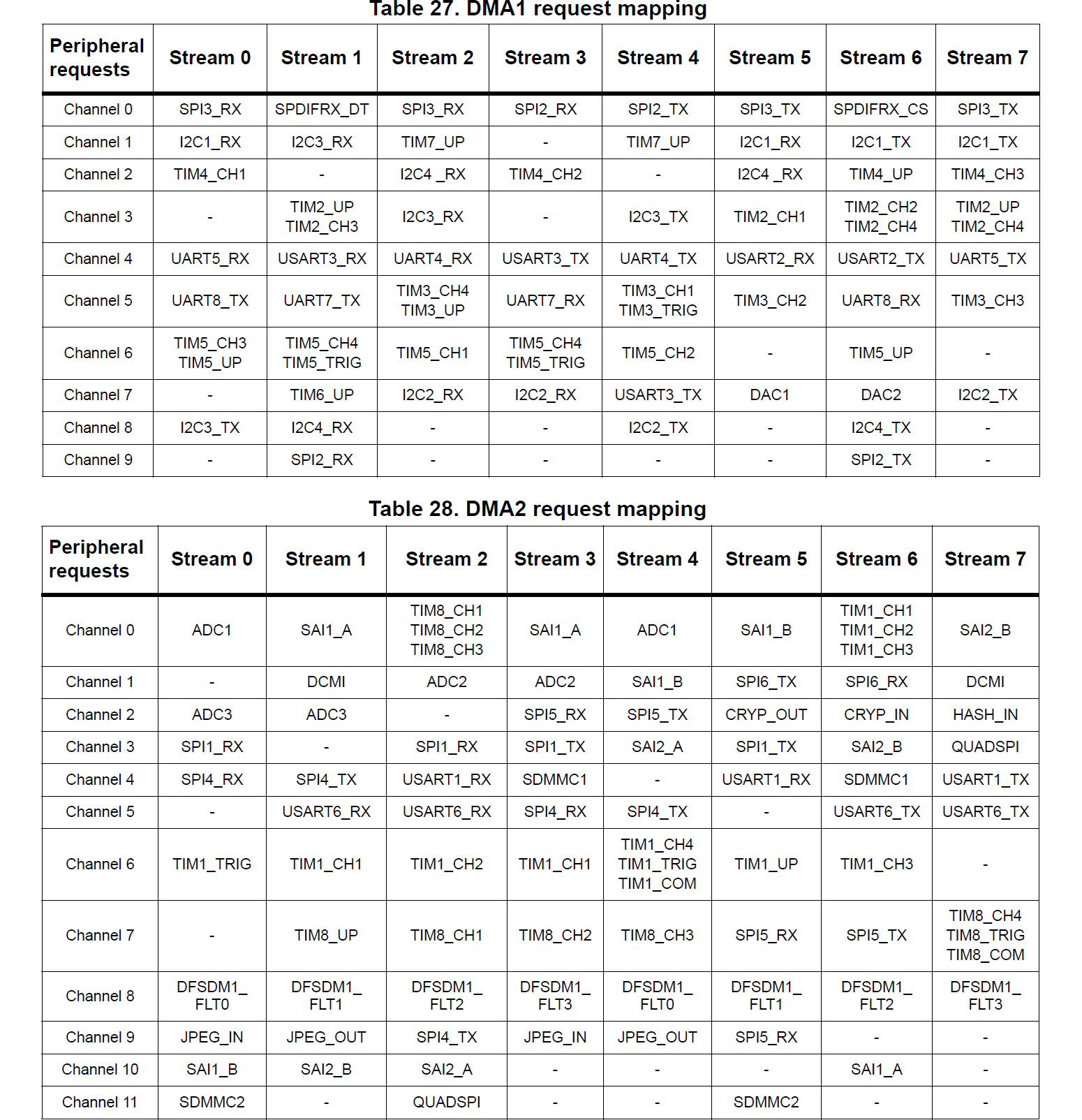
The reference manual uses two terms that are confusing the first time you see them:
DMA streams are best thought of as potential interrupt sources, since that’s the way you usually interact with them at a software level. They represent independent transfer capabilities within a DMA controller, and each stream can be attached to one of a small set of peripherals by associating a DMA channel with the stream.
DMA channels are the connections between the DMA controller and a specific peripheral.
An example might make this clearer. Suppose you want to do DMA
transfers for receiving data from USART1. Locate
USART1_RX in the tables above, and you’ll see two entries in
the DMA2 table, one for “Stream 2, Channel 4” and one for
“Stream 5, Channel 4”.
Let’s say we decide to use stream 2. We can enable DMA for
USART1_RX by selecting channel 4 for stream 2 on DMA2 by
assigning the value 4 to the CHSEL channel selection field of
the DMA2->S2CR configuration register. Once this is done and
the rest of the DMA configuration is complete, DMA2_Stream2
interrupts will occur when DMA transfers from USART1 to memory
complete.
A DMA stream is a source of interrupts from the DMA controller. A DMA channel is a connection between a peripheral and a DMA controller.
If you look carefully at the tables above, you’ll see that you can’t
use DMA with all the peripherals on the STM32F767 at the same time.
The table for DMA1 lists 51 distinct peripheral connections,
and the table for DMA1 lists 46 distinct peripherals, but each
of DMA1 and DMA2 only have 8 DMA streams that can be
assigned to peripherals at any one time. There is some redundancy of
assignments, to help with using DMA with multiple peripherals at the
same time, but you still need to think carefully to make sure that
it’s possible to set up DMA for all the peripherals you want to use it
with.
This is especially true for some peripherals that can only be attached
to a single DMA stream. For example, if you want to use DMA with the
STM32F767’s cryptographic processor (for AES encryption and
decryption, say), you need to assign streams 5 and 6 on DMA2,
since the CRYP_IN and CRYP_OUT peripheral connections
aren’t available on any other streams. If you also want to do JPEG
encoding and decoding, you need to assign either streams 0 and 1, 0
and 4, 3 and 1 or 3 and 4 (those are the combinations that cover the
JPEG_IN and JPEG_OUT peripheral connections). Once
you’ve done that, you can no longer use DMA with both of the
SD/SDIO/MMC interfaces (for reading and writing SD cards and eMMC
devices), since whichever streams you assign to the JPEG codec block
off the remaining available stream for one of the SD/SDIO/MMC
controllers.
You can switch DMA stream assignments around as you need to, but doing that definitely complicates your code, and it’s much easier to work with a static assignment of peripherals to DMA streams when you can. Just be aware that that’s not always possible, and it may require some headscratching and careful examination of the tables above to work out a good assignment.
(This discussion is specific to the STM32F7 microcontrollers. The DMA
controller in the STM32H7 MCUs, for example, is more convenient to
use, because the DMA controller is split from the stream/channel
assignment system, which lives in a separate DMAMUX DMA
multiplexer peripheral. That means you can assign any peripheral to
any stream, which makes life simpler.)
DMA and ADC
For our use case, we need a single DMA stream connected to the
ADC1 peripheral. ADC1 appears in the DMA2 table
above, and is available on stream 0, channel 0 or stream 0, channel 4.
We’ll use stream 0, channel 0 for our examples.
This means that we will receive interrupts from the DMA2 DMA
controller via the DMA2_Stream0_IRQHandler interrupt service
routine. We can check DMA controller status flags in that interrupt
handler to determine whether we have a DMA error or a “transfer
complete” event. (It’s also possible to be notified when a transfer is
half complete, which is useful for keeping the DMA FIFOs full if
you’re using them.)
We’ll now look at two examples of how to set this up.
Example 2: DMA ADC for a single input
In our
first
DMA example, which is in ex2.c, we’re going to collect a
single ADC sample using DMA, triggered on a button press. The
effective result of this will be identical to our first polled ADC
example, but it will give us a basis for doing more interesting
things.
ADC configuration
There is no difference in the ADC configuration to the polled ADC example. Management of the ADC’s DMA mode is done when triggering the conversion, because the ADC’s DMA enable state needs to be reset between conversions.
DMA configuration
There are six steps to setting up the DMA controller:
1. Enable DMA peripheral clock.
You need to enable the peripheral clock for the DMA controller, otherwise it won’t do anything at all. It might seem strange to think of a DMA controller as a peripheral, but it’s a bit of silicon in the MCU that can be powered on or off independently, so it has a peripheral clock to do that.
We do this in the same way as for other peripherals. The DMA controllers are on the AHB1 bus:
volatile uint32_t tmpreg;
  SET_BIT(RCC->AHB1ENR, RCC_AHB1ENR_DMA2EN);
  tmpreg = READ_BIT(RCC->AHB1ENR, RCC_AHB1ENR_DMA2EN);
  (void)tmpreg;
2. Select peripheral channel for DMA stream
We need to set up the association between the DMA stream we’re using
(stream 0 on controller DMA2) and the channel, i.e. the
peripheral, we want to connect that stream to. This is handled by
assigning a channel number to the CHSEL channel selection field
of the DMA2_Stream0->CR configuration register:
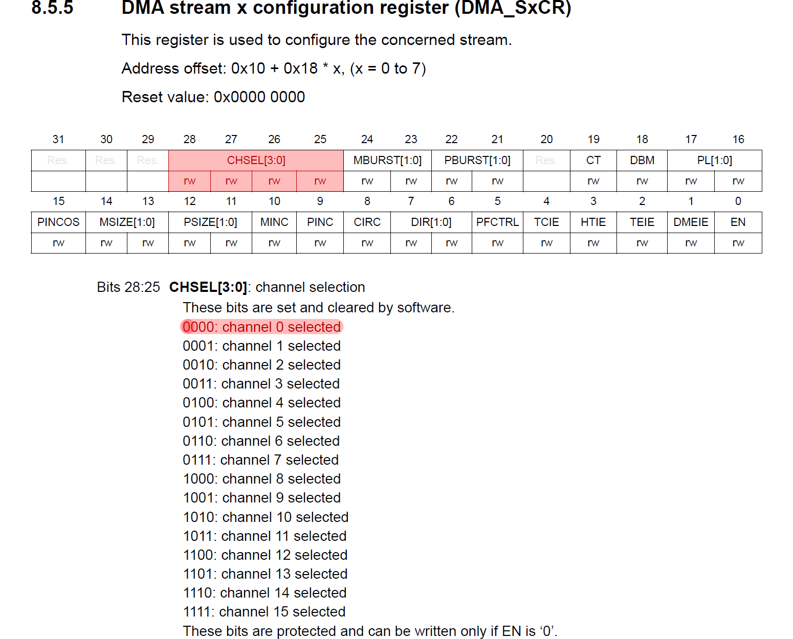
We want channel 0 (from the “DMA2 request mapping” table we
looked at earlier), so we do this:
MODIFY_REG(DMA2_Stream0->CR, DMA_SxCR_CHSEL, 0x00);3. Configure DMA transfer
The DMA controller has lots of options to control how transfers
happen. These options are all set in the per-stream CR
configuration register, i.e. in DMA2_Stream0->CR for our case.
Here’s what we do (we’ll talk through the options below):
MODIFY_REG(DMA2_Stream0->CR,
             DMA_SxCR_DIR | DMA_SxCR_CIRC | DMA_SxCR_PINC | DMA_SxCR_MINC |
             DMA_SxCR_PSIZE | DMA_SxCR_MSIZE | DMA_SxCR_PL | DMA_SxCR_PFCTRL,
             0x00000000U |      // Direction: peripheral to memory
             0x00000000U |      // Peripheral: no increment
             DMA_SxCR_MINC |    // Memory: increment
             DMA_SxCR_PSIZE_0 | // Peripheral data align: halfword
             DMA_SxCR_MSIZE_0 | // Memory data align: halfword
             DMA_SxCR_CIRC |    // Mode: circular
             DMA_SxCR_PL_1);    // Priority: high
We want:
DMA direction: from peripheral to memory;
Address increment: no increment at the peripheral end (because we’re just going to read data from the fixed address of the
ADC1->DRdata register); enable increment at the memory end (because we’re going to want to put ADC samples into a memory buffer one after another);Transfer data sizes: ADC samples are 12 bits wide, so we use half-word transfers (i.e. 16 bits) at both ends — it’s possible to get the DMA controller to do various kinds of data packing and unpacking as it transfers data, but we don’t need that here;
Circular mode: this is an option that allows us to start the ADC+DMA conversion and transfer process repeatedly, which is useful if you don’t need to change any setup between conversions;
Transfer priority: we don’t care much here, since we’re just doing one DMA transfer, so we’ll set it to high.
Figuring out how to set all these options can be hard work. It’s worth read Section 8 of the reference manual carefully. This describes everything the DMA controllers can do.
4. Set DMA transfer addresses and size
The other options we need to set for the DMA controller are the most
important: the base source and destination addresses we’re using and
the number of items we want to transfer. For the addresses, our source
is the ADC1->DR data register of the ADC, and the destination
is the address of a normal variable that we’ve defined:
static volatile uint16_t dma_adc_sample;

  ...

  WRITE_REG(DMA2_Stream0->PAR, (uint32_t)&(ADC1->DR));
  WRITE_REG(DMA2_Stream0->M0AR, (uint32_t)&dma_adc_sample);
In this example, we’re only going to do a single conversion from a
single analog input, so we only need a single uint16_t value to
store our conversion results. And we tell the DMA controller to
perform only a single transfer by setting the DMA streams NDTR
register:
MODIFY_REG(DMA2_Stream0->NDTR, DMA_SxNDT, 1);This register decrements after each item is transferred on the DMA
stream. When it reaches zero, a DMA transfer complete interrupt is
triggered (if enabled) and, if circular mode is enabled for the
stream, the previously loaded item count value is reloaded. This means
that we can set NDTR once, then trigger DMA transfers by
starting the ADC conversion process, and the right number of values
will be transferred each time.
5. Enable DMA interrupts
We want to get DMA interrupts to be notified when a conversion and transfer completes. As usual, we need to enable the relevant interrupts with the NVIC:
NVIC_SetPriority(DMA2_Stream0_IRQn, 1); // DMA IRQ lower priority than ADC IRQ.
  NVIC_EnableIRQ(DMA2_Stream0_IRQn);
and to set some peripheral-dependent interrupt enable bits:
SET_BIT(DMA2_Stream0->CR, DMA_SxCR_TCIE);
  SET_BIT(DMA2_Stream0->CR, DMA_SxCR_TEIE);
In this case, we enable the “transfer complete” and “transfer error”
interrupts. This means that when we get a DMA2_Stream0
interrupt, we need to examine some flags in the stream’s interrupt
status register to determine the reason for the interrupt:
void DMA2_Stream0_IRQHandler(void) {
  // DMA transfer complete.
  if (READ_BIT(DMA2->LISR, DMA_LISR_TCIF0)) {
    WRITE_REG(DMA2->LIFCR , DMA_LIFCR_CTCIF0);
    dma_complete = true;
  }

  // DMA transfer error.
  if (READ_BIT(DMA2->LISR ,DMA_LISR_TEIF0)) {
    WRITE_REG(DMA2->LIFCR , DMA_LIFCR_CTEIF0);
    dma_error = true;
  }
}
6. Enable DMA transfer
Finally, we need to actually enable the DMA stream, which we do by
setting the EN bit in the stream’s CR configuration
register:
SET_BIT(DMA2_Stream0->CR, DMA_SxCR_EN);Triggering ADC with DMA
Before we trigger an ADC conversion by setting the SWSTART bit
in the ADC’s CR2 register (just as we did for the polled ADC
case), we need to enable the connection between the ADC and the DMA
controller on the ADC end. We do this by clearing and then immediately
setting the DMA bit in the ADC’s CR2 register:
CLEAR_BIT(ADC1->CR2, ADC_CR2_DMA);
  SET_BIT(ADC1->CR2, ADC_CR2_DMA);
Setting the DMA bit causes a DMA transfer to be triggered after
each ADC conversion. Clearing the DMA bit before setting it is
needed to reset the ADC-DMA link in between rounds of conversion.
Working out what’s going on here requires some careful reading of the
STM32F767 reference manual. Section 15.8.1 (Using the DMA) in the
ADC chapter of the manual includes the following description:
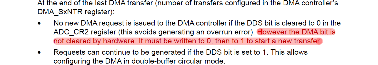
The important part here is “However the DMA bit is not cleared
by hardware. It must be written to 0, then to 1 to start a new
transfer.” That’s what we’re doing here. We don’t want to set the
DDS bit, because we want DMA transfers to stop once we’ve
transferred the number of items that we configure, and we’re not using
any double-buffering.
Once we reset the DMA bit in the ADC1->CR2 register like
this, we set the SWSTART bit:
SET_BIT(ADC1->CR2, ADC_CR2_SWSTART);and the ADC conversion starts, just as in the polled case. However, in
this case, we do not wait for the ADC to mark that the conversion
has been completed by polling on the EOC bit in the
ADC1->SR status register. Instead we go straight back to the
main loop of our program.
When the ADC conversion is complete, the ADC tells the DMA controller
to start a transfer, and the way that we’ve configured the DMA
controller causes the contents of the ADC’s conversion data register
ADC1->DR to be transferred to the buffer we set up. Since we
configured stream 0 on DMA2 to transfer only a single item, as
soon as the single conversion result is transferred, the DMA
controller raises a DMA2_Stream0 “transfer complete” interrupt.
We use this to indicate that the ADC conversion is complete and the
conversion result is available in our buffer.
(As for the all the examples here, the main program for ex2.c
is just a super-loop that uses flags set by interrupt service routines
to respond to external events. For example, there is a
dma_complete flag that’s set in the DMA2_Stream0 ISR
that’s used to trigger printing of the ADC conversion results.)
Example 3: DMA ADC for multiple inputs
Using DMA to transfer a single value isn’t very exciting, so
example
ex3.c uses the same approach to convert four analog inputs one
after another. The DMA controller transfers the ADC conversion results
to a buffer and generates an interrupt once all four conversions are
done. The main program can then retrieve the converted data from the
buffer.
There are relatively few configuration differences compared to the last example to make this work.
ADC configuration
First we need to ensure that GPIO pins we want to use are configured as analog inputs. This is done in the common configuration code.
We then need to configure the ADC to do multiple conversions. First we
need to set the number of input signals we need to convert in the
L length field of the ADC’s SQR1 register:
MODIFY_REG(ADC1->SQR1, ADC_SQR1_L, (4 - 1) << ADC_SQR1_L_Pos);The values in the L field are one less than the number of
inputs we want to convert: we set this field to zero to do a single
conversion, and to do four conversions we set L=3.
We then need to let the ADC know which inputs to convert. We do
this by writing channel indexes (from 4 to 7, which are the ADC
channels that are connected to the GPIOs that we’re using) into the
SQn fields of the ADC’s SQR1, SQR2, and
SQR3 registers. Remember that these sequence registers are
arranged backwards, i.e. the first input to be converted goes in
the last (least significant bits) position in SQR3, the second
channel goes in the next higher bit position field, and so on, moving
back to SQR2 and SQR1 for the later fields. We have four
fields, and the channel indexes for those all fit into SQR3, so
we do:
MODIFY_REG(ADC1->SQR3, ADC_SQR3_SQ1, 0x04 << ADC_SQR3_SQ1_Pos);
  MODIFY_REG(ADC1->SQR3, ADC_SQR3_SQ2, 0x05 << ADC_SQR3_SQ2_Pos);
  MODIFY_REG(ADC1->SQR3, ADC_SQR3_SQ3, 0x06 << ADC_SQR3_SQ3_Pos);
  MODIFY_REG(ADC1->SQR3, ADC_SQR3_SQ4, 0x07 << ADC_SQR3_SQ4_Pos);
We then need to set sample times for each of the channels we’re using:
MODIFY_REG(ADC1->SMPR2, ADC_SMPR2_SMP4, 0x03 << ADC_SMPR2_SMP4_Pos);
  MODIFY_REG(ADC1->SMPR2, ADC_SMPR2_SMP5, 0x03 << ADC_SMPR2_SMP5_Pos);
  MODIFY_REG(ADC1->SMPR2, ADC_SMPR2_SMP6, 0x03 << ADC_SMPR2_SMP6_Pos);
  MODIFY_REG(ADC1->SMPR2, ADC_SMPR2_SMP7, 0x03 << ADC_SMPR2_SMP7_Pos);
Finally, we need to enable scan mode. This is the mode that makes
use of the SQR1, SQR2 and SQR3 registers to
decide which channels to convert:
SET_BIT(ADC1->CR1, ADC_CR1_SCAN);DMA configuration
The only change to the DMA configuration here compared to ex2.c
is that we need to define a larger buffer to store the converted
samples:
#define NCHANNELS 4
static volatile uint16_t dma_adc_sample[NCHANNELS];
we need to set the DMA destination memory address correctly:
WRITE_REG(DMA2_Stream0->M0AR, (uint32_t)&dma_adc_sample[0]);and we need to set the DMA transfer size to the number of items we want to convert:
MODIFY_REG(DMA2_Stream0->NDTR, DMA_SxNDT, NCHANNELS);Triggering ADC with DMA
We start an ADC conversion exactly as for the previous example,
resetting the ADC’s DMA flag, then setting the SWSTART
bit in the ADC1->CR2 register:
CLEAR_BIT(ADC1->CR2, ADC_CR2_DMA);
  SET_BIT(ADC1->CR2, ADC_CR2_DMA);

  SET_BIT(ADC1->CR2, ADC_CR2_SWSTART);
When we do this, four ADC conversions are performed one after another
on the four analog inputs that we specified, and after each conversion
completes, a DMA transfer is triggered to move the conversion result
into our buffer. Once all four conversion results have been
transferred, the DMA controller raises a “transfer complete”
interrupt. In the interrupt handler for the DMA interrupt, we set a
dma_complete flag, and use this in the main program super-loop
to detect when there is new data available in the buffer.
Conclusions
The biggest obstacle to making DMA work is just wading through the documentation for all the options supported by the STM32F767’s DMA controllers. Once you settle on one specific setup, and get some understanding of the assignment of DMA channels (DMA controller to peripheral connections) to DMA streams (distinct DMA processing engines within the DMA controllers that can serve as interrupt sources), it’s not too hard to get things going.
In the next
article, we’ll tie all this up by changing from triggering ADC
conversions from software (using the SWSTART bit in the
ADC1->CR2 register) to triggering them with a timer. As a
reward for getting through all this rather dry material, we’ll also
write a (tiny and useless) USB oscilloscope application!